
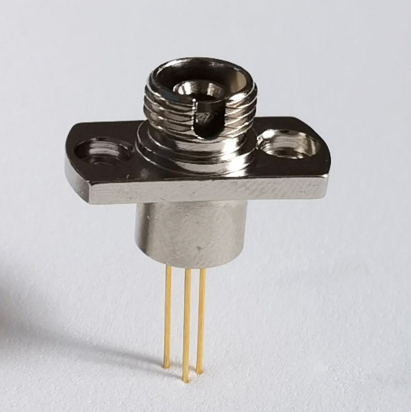
When selecting an FC-connectorized InGaAs PIN photodiode without an integrated transimpedance amplifier (TIA), the key factors are active area, dark current, junction capacitance, bandwidth, and fiber-coupling tolerance.
1. How Does Active Area Affect Performance?
A smaller active area generally provides lower dark current and junction capacitance, resulting in lower detector noise contributions and potentially higher bandwidth. However, actual performance depends on the device design, reverse bias, and operating temperature.
A larger active area offers greater alignment tolerance, making fiber coupling and assembly easier.
Ø150 μm: Low Capacitance and High Bandwidth
A 150 μm detector is worth considering for applications requiring low capacitance and high bandwidth, provided the optical spot is well controlled.
Its smaller active area requires more precise optical alignment. The fiber core diameter alone does not determine the spot size at the detector, so the internal optical path and coupling geometry must also be considered.
Ø300 μm: A Good General-Purpose Choice
A 300 μm detector often provides a practical balance between electrical performance and coupling tolerance. It is a good starting point for standard single-mode fiber power-monitoring applications.
Ø500 μm: More Forgiving Alignment
A 500 μm detector provides a larger alignment margin and is useful when optical alignment is less precise or the beam spot is larger. The trade-off is typically higher junction capacitance and potentially lower bandwidth.
Ø1000 μm: For Large Spots and Lower Bandwidth
A 1000 μm detector offers generous coupling tolerance but generally has higher capacitance. Check its dark current and capacitance at the intended operating bias rather than relying on zero-bias specifications.
2. How Should Dark Current Be Compared?
Dark current is the leakage current measured in the absence of incident light. It contributes to measurement offset and shot noise, which can be important in low-light applications.
When comparing detectors, always check:
- Dark current at the same reverse bias and temperature.
- Junction capacitance at the intended operating bias.
- Responsivity at the target wavelength.
- TIA input noise and the required measurement bandwidth.
A lower dark current is desirable, but it does not automatically guarantee a lower system noise floor. The external TIA and the measurement bandwidth also matter.
For example, at −70 dBm, the optical power is 0.1 nW. At a responsivity of 0.9 A/W, this produces only about 90 pA of photocurrent. Whether this signal can be measured reliably depends on the complete detector and readout circuit.
3. How Is a Bare Photodiode Connected?
An InGaAs PIN photodiode without a built-in TIA outputs photocurrent, not a buffered voltage signal. An external TIA is normally used to convert this current into a measurable voltage.
A common configuration uses reverse bias:
- Apply the specified reverse-bias voltage across the photodiode.
- Connect the output electrode to the TIA input, typically held near virtual ground.
- Feed the TIA voltage output into an ADC or data-acquisition system.
For a common polarity, the cathode is connected to a positive bias supply and the anode to the TIA’s inverting input. Confirm the pinout and bias limits in the device datasheet.
Reverse bias generally reduces junction capacitance and improves speed, but may increase dark current. Zero-bias operation is also valid and can be advantageous for low-noise measurements when the required bandwidth and readout circuit permit it.
A 50 Ω load specified for bandwidth or rise-time testing is a measurement condition, not a universal requirement for the external TIA.
4. What Should Be Considered for FC Fiber Coupling?
FC/APC connectors can help reduce back-reflections compared with FC/UPC connections. They are worth considering when optical return loss matters.
The fiber-to-detector optical path should be mechanically stable to minimize coupling changes caused by vibration or temperature variation.
When converting a free-space or flange-mounted detector design to an FC-coupled version, verify the optical coupling efficiency and recalibrate the assembled system. Previous calibration coefficients may no longer be valid.
Practical recommendation: Start with a 300 μm detector for a general-purpose design, consider 150 μm when lower capacitance and tighter optical alignment are acceptable, and choose a larger active area when coupling tolerance is the priority. Always make the final decision using datasheet values measured under the intended operating conditions.