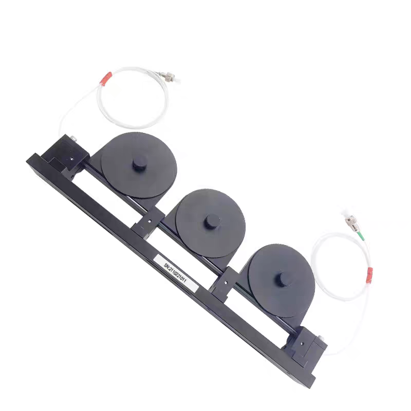
In the world of fiber optics, managing the state of polarization (SOP) is critical—whether you are working with fiber lasers, interferometers, or PDL measurement systems. The Mechanical 3-Paddle Polarization Controller (MPC) remains one of the most reliable, cost-effective, and intuitive tools for this purpose.
I. How It Works: The Physics of Birefringence
The MPC functions based on stress-induced birefringence. By winding the fiber around circular mandrels (the paddles), you introduce mechanical stress into the fiber core. This stress changes the refractive index, causing the light to experience a phase delay based on the orientation and number of fiber loops.
The device is designed as a sequence of three paddles, acting as waveplates:
- Paddle 1 (λ/4): Converts input light into a specific polarization state.
- Paddle 2 (λ/2): Rotates the polarization angle.
- Paddle 3 (λ/4): Transforms the light into any arbitrary polarization state (including linear, circular, or elliptical).
Pro-Tip: The delay effect is governed by the cladding radius, the winding radius of the mandrel, and the operating wavelength. Always ensure your winding pattern matches your operating wavelength for optimal performance.
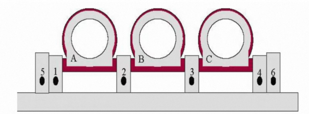
II. Assembly Guide: The 3-6-3 Configuration
For a standard 1550 nm operating wavelength using 900 µm jacketed single-mode fiber (like SMF-28e), use the 3-6-3 winding pattern.
Preparation
- Prepare the Hardware: Remove rubber stops A, B, and C. Ensure screws 1–4 are tightened, and screws 5 and 6 are loosened.
- Positioning: Rotate all three paddle plates to the “front” position.
Fiber Installation
- Fiber Prep: Cut a section of single-mode fiber (at least 1 meter long). Avoid twisting the fiber during installation.
- Anchor the Input: Place the fiber end on stopper A, press down, and tighten screw 6.
- Wind the Loops:
- Paddle 1: Wrap the fiber around the groove 3 times. Ensure the fiber is flat and untwisted.
- Paddle 2: Wrap the fiber around the groove 6 times. Return the rubber stopper to its position to secure the loop.
- Paddle 3: Wrap the fiber around the groove 3 times. Return the rubber stopper to its position.
- Anchor the Output: Place the fiber on stopper B, press down, and tighten screw 5.
III. Performance Specifications
The mechanical structure is optimized for stability and minimal loss. Below are the standard specifications for a typical 3-paddle unit.
| Parameter | Specification |
| Structure | Triple-ring (Paddle) |
| Operating Wavelength | 1290 nm – 1610 nm |
| Insertion Loss (Typ/Max) | 0.7 dB / 1.0 dB |
| Fiber Type | SMF-28e |
| Fiber Cladding Diameter | 125 μm |
| Paddle Diameter | 56 mm |
| Recommended Winding | 3-6-3 |
| Return Loss | >50 dB |
| Rated Power | 500 mW |
| Operating Temperature | 0°C to +70°C |
IV. Operational Tips
- Achieving Polarization Control: By rotating the λ/2 and λ/4 waveplate paddles (each can be rotated 180°), you can sweep through all possible states of polarization.
- Mechanical Structure: * Total Length: 273 mm
- Spacing Between Rings: 78 mm
- Overall Height: 38 mm
Mastering the MPC takes a bit of practice. Start by observing the output on a polarimeter or by monitoring signal intensity at a downstream detector, and rotate the paddles slowly to understand the mapping of your input signal to the desired output state.