In the world of CATV and HFC (Hybrid Fiber-Coax) networks, maintaining signal integrity during the optoelectronic conversion of RF signals is paramount. Today, we’re diving into the technical implementation of Online Optical Power Monitoring, focusing on why FC-flanged InGaAs Photodiodes (PDs) and 1×2 10/90 Couplers are the industry’s “dynamic duo.”
The Core Components: Why InGaAs?
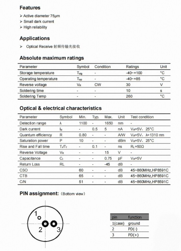
When working in the near-infrared (NIR) spectrum (1100–1650 nm), material choice is everything. While Silicon photodiodes are excellent for visible light, they fail completely beyond 1100 nm.
For O-band (1310 nm) and C/L-band (1550 nm) fiber communications, InGaAs (Indium Gallium Arsenide) is the gold standard. It offers:
- High Responsivity: Optimized for 1310/1550 nm windows.
- High Speed: With rise/fall times of ~0.1 ns and low capacitance (approx. 0.75 pF), these diodes can handle high-frequency RF signals across the 45 MHz to 1.2 GHz range.
- Linearity: Essential for maintaining critical CATV metrics like CSO (Composite Second Order), CTB (Composite Triple Beat), and C/N (Carrier-to-Noise Ratio).
Practical Application: The 10/90 Monitoring Topology
The most common setup for online monitoring involves tapping a small portion of the signal without disrupting the main transmission.
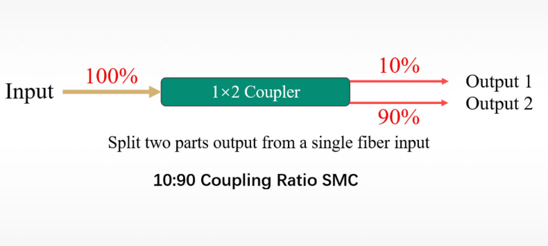
1. The “Golden Ratio” Coupler
We use a 1×2 10/90 FBT or PLC Coupler.
- 90% Path (Through): Carries the main service signal to the optical receiver with minimal insertion loss (~0.5 dB).
- 10% Path (Tap): Redirected to the InGaAs PD for real-time power monitoring. This balance ensures the monitoring signal is strong enough to provide a stable voltage reading without starving the main RF output.
2. Connection Procedures
To ensure a professional installation, follow these steps:
- Optical Hygiene: Use lint-free wipes and anhydrous alcohol to clean all FC/APC or FC/PC end faces. Dust on the PD surface can cause “hot spots” or signal scattering.
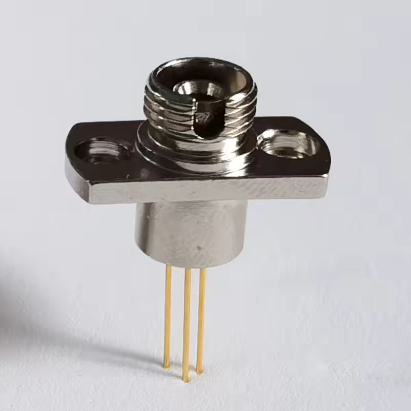
- Mechanical Coupling: Align the FC male connector of the coupler with the PD’s female flange. Rotate the locking nut clockwise until finger-tight to prevent air gaps that cause Fresnel reflections.
- Circuit Integration:
- Bias: Connect the Cathode to a stable +5V reverse bias.
- Signal: Connect the Anode to the input of a Transimpedance Amplifier (TIA).
- Ground: Ensure the flange housing is properly