
When engineers first examine an Optical Circuit Switch (OCS), the initial intuition is often deceptively simple:
“Isn’t it just a tiny MEMS mirror pivoting in free space to reflect light into another fiber? How hard can that be?”
Having spent considerable time working alongside OCS hardware, specialized optical fiber bundles, and high-precision fiber array assemblies, I can assure you that the primary engineering bottleneck isn’t getting the micro-mirror to tilt. The true challenge lies in coupling light back into a micron-scale fiber core with sub-2dB insertion loss, reliably, continuously, and across years of operation in modern AI data centers.
In this two-part technical deep dive, I want to share my notes on why OCS and single-mode fibers are fundamentally tied together. In Part 1, we will explore why multi-mode fiber (MMF)—despite its appealing large core—was ruled out early during hardware prototyping.
1. The Symbiotic Reality of OCS & Optical Fiber
An Optical Circuit Switch generates no light signals of its own. It serves strictly as a physical-layer dynamic fiber path scheduler. From early conceptual prototyping to massive industrial deployment in hyperscale AI compute clusters, OCS architecture and optical fiber manufacturing have advanced in lockstep.
At the core of a MEMS-based OCS, free-space optics dictate that every photon exiting an input fiber must be collimated, reflected off a microscopic mirror array, and focused back into a target output fiber core. Fiber is the sole transmission medium.
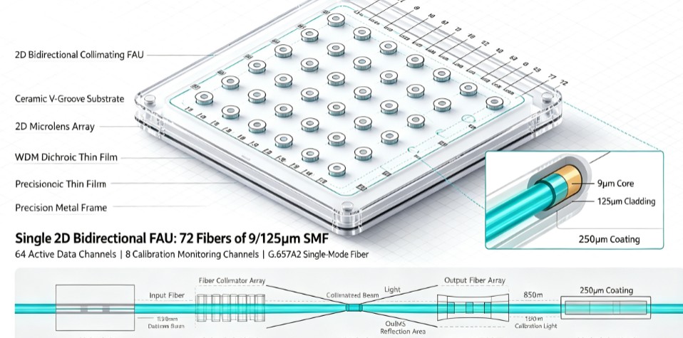
The Industrialization Bottleneck: Aligning input fiber arrays, micro-lens arrays, and 2D MEMS mirror arrays requires sub-micron (/um) or even nanometer-level tolerances across dozens of optical channels simultaneously.
2. Deep Dive: Why Multi-Mode Fiber (MMF) Fails in OCS
A question frequently raised during architectural design reviews is: Why not leverage Multi-Mode Fiber (MMF) with its larger 50um core to loosen alignment tolerances and lower manufacturing cost?
In practice, multi-mode fiber was ruled out early due to fundamental physical constraints:
| Parameter / Feature | Multi-Mode Fiber (MMF – 50µm) | Single-Mode Fiber (SMF – G.657.A2) |
| Insertion Loss (IL) | High: 5.0 – 10.0 dB | Ultra-Low: < 2.0 dB Target |
| Beam Focusing & Waist | Large waist, multi-mode phase mismatch | Gaussian profile, clean diffraction limit |
| Wavelength Support | Short-reach (SR) 850 nm only | Full transparency across O, E, S, C, L bands |
| Transceiver Compatibility | Incompatible with 800G/1.6T LR4 | Native fit for high-speed AI optical modules |
A. Physical Beam Waist & Modal Dispersion
Because MMF supports multiple spatial modes, light exiting an MMF core does not form a clean, single-mode Gaussian beam. When reflected through free space across a MEMS mirror array, the large beam waist and inter-modal interference make it mathematically and physically impossible for the lens array to refocus the light back into an output core efficiently. This results in an overwhelming insertion loss of 5–10 dB—completely violating the stringent < 2 dB insertion loss budget required by high-density AI clusters.
B. Wavelength & Speed Limitations
Multi-mode fiber is inherently tailored for 850 nm short-reach (SR) VCSEL transceivers. Modern AI compute platforms rely heavily on 800G and 1.6T transceivers (such as 800G LR4 or CWDM4) operating at 1310 nm (O-band) or 1550 nm (C-band). G.657.A2 single-mode fiber delivers wavelength transparency across all telecom bands, allowing seamless WDM scaling and future-proof throughput.
Coming Up in Part 2…
Now that we’ve covered why multi-mode fiber fails the physics test, how do we actually bring single-mode fibers into OCS in real-world manufacturing? In Part 2, we will dive into the core interface component—2D Collimating Fiber Array Units (2D FAUs)—and break down the exact fiber counts required for commercial 32×32 and 64×64 OCS machines. Stay tuned!