If you’re working with Distributed Feedback (DFB) lasers, understanding the pin functions of the Thermal Electric Cooler (TEC) and laser module is non-negotiable. These pins are the backbone of two critical systems: temperature stabilization (to keep wavelength consistent) and power regulation (to maintain reliable light output). Let’s break down their logic step by step.
1. TEC Pins: The Unsung Heroes of Temperature Stability
DFB lasers are notoriously temperature-sensitive—even tiny thermal fluctuations can drift their wavelength. That’s where the TEC comes in: it acts as a “thermal thermostat” for the laser. Here’s how its pins work:
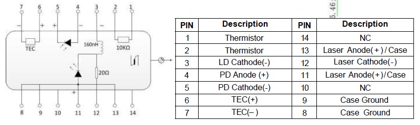
- Positive Terminal (TEC (+)): Pin 6
- Negative Terminal (TEC (-)): Pin 7
By applying current across Pins 6 and 7, the TEC switches between “cooling” and “heating” modes. But it doesn’t work alone:
👉 Pins 1 and 2 connect to a thermistor that detects the laser’s internal temperature, sending a real-time feedback signal. Together, the TEC and thermistor form a closed-loop temperature control system—ensuring the DFB operates at a rock-steady temperature and suppressing wavelength drift.
2. DFB Laser Pins: Driving & Stabilizing Light Output
As the core light-emitting component, the DFB’s pins are all about delivering precise power and maintaining consistency:
Drive Current Pins (Power Input)
- Negative Terminal (Laser (-)): Pins 3 + 12
- Positive Terminal (Laser (+)): Pins 11 + 13
These pins accept the laser’s drive current—tweak the current magnitude, and you directly control the laser’s output power.
Power Monitoring Pins (Feedback Loop)
Pins 4 and 5 host a Monitoring Photodiode (MPD):
- MPD (+): Pin 4
- MPD (-): Pin 5
The MPD continuously tracks the laser’s output power, feeding data back to form a power closed-loop system. When combined with the TEC’s temperature loop, this dual feedback mechanism guarantees the DFB’s signature “narrow linewidth + stable power” performance.
3. Auxiliary Pins: The Supporting Cast That Matters
Don’t overlook these pins—they’re critical for system reliability:
- Thermistor (Pins 1-2): Feeds temperature data to the TEC’s closed-loop (we covered this earlier, but it’s worth highlighting as an auxiliary star).
- MPD (Pins 4-5): Powers the power feedback loop (another hardworking auxiliary component).
- Case Ground (Pins 8-9): Provides electromagnetic shielding to minimize external interference—key for keeping laser output clean.
- Null Pins (Pins 10-14): No specific functions yet—reserved for future upgrades or left floating.
Wrapping Up: The Big Picture
Every pin in this system is designed with one goal: to maximize the DFB laser’s strengths (narrow linewidth, stable wavelength, consistent power). By pairing the TEC + thermistor (temperature control) with the MPD + driver circuit (power control), the pin layout creates a robust, multi-loop system that keeps the laser performing at its best.
Next time you’re debugging or designing with a DFB laser, refer back to this breakdown—understanding these pins will save you time and headaches!