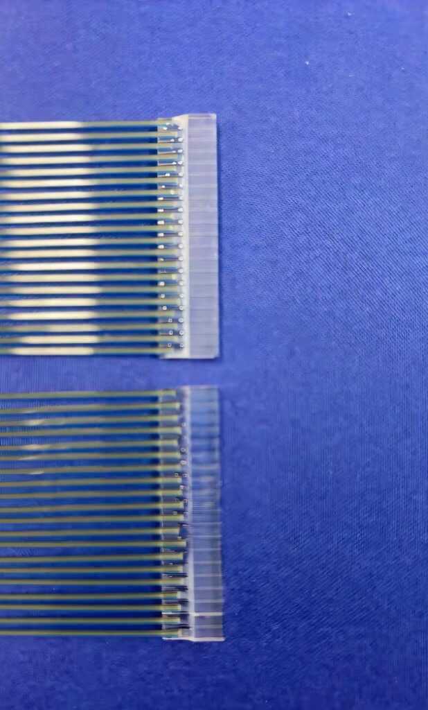
Fiber Array (FA) is a crucial component in optical communication systems. It utilizes a V-Groove substrate, with a bundle of optical fibers or a fiber strip installed at specific intervals to form the array.
In optical communications, fiber arrays mainly consist of substrates, platens, and optical fibers. Typically, multiple grooves are precisely cut on the base of the substrate. The platen then presses and secures the optical fibers that are inserted into these grooves. The materials and manufacturing processes of fiber optic arrays demand extremely high precision.
Fiber optic arrays predominantly rely on precision-engraved V-grooves for accurate positioning. A specialized cutting process is necessary to achieve precise fiber placement. The bare fiber section, where the fiber coating has been removed, is placed within the V-groove.
Once the bare fiber portion (with the coating removed) is positioned in the V-groove, it is pressurized by a pressurizer component and bonded with adhesive. At the front end, the fiber undergoes precise positioning for connection to the Planar Lightwave Circuit (PLC). This process requires ultra-precision machining to accurately position the fiber core within the V-groove, thereby minimizing connection losses. After that, it is pressurized by the pressurizer component and fixed with adhesive, and the end faces are optically ground to form the fiber array. The substrate material plays a vital role in influencing the optical properties of the fiber array. A material with a low coefficient of expansion is preferred to ensure a stress-free fiber array, high reliability, and prevent fiber displacement at high temperatures. Commonly used materials include glass and silicon, while ceramics, conductive substrates, and plastic substrates are also viable options.
The distance between the grooves, the number of fiber channels, and the grinding angle of the V-groove can all be customized according to specific needs. However, the center-to-center dimensions between adjacent grooves are accurate to ± 0.5 μm, and the parallelism of the grooves between adjacent grooves in the length direction of the grooves is within ± 0.1 degrees.
The optical fibers used in the FA are mostly colorful ribbons. These ribbons offer excellent bending resistance, and the multicolored appearance allows for easy differentiation between channels.
Features of Fiber Optic Arrays:
- High-precision core spacing: Ensures accurate alignment of fiber cores for efficient signal transmission.
- Up to 256-channel fiber array: Provides a high channel capacity to meet the increasing demand for data transmission.
- High stability and reliability: Maintains consistent performance over time, reducing the risk of failures in optical communication systems.
- Low insertion loss: Minimizes the loss of optical signals during transmission, improving overall system efficiency.
Fiber optic arrays find wide applications in various fields such as planar optical waveguides, array waveguide gratings, active/passive array fiber optic devices, and microelectromechanical systems; as well as in multi-channel optical modules. In particular, fiber optic arrays are one of the important components of the Planar Lightwave Circuit Splitter (PLC Splitter). They can significantly reduce the loss of optical waveguide devices and facilitate optical coupling alignment.
When selecting substrate materials, those with a small coefficient of expansion, like glass and silicon, are recommended to guarantee the stability and reliability of the fiber array.
The operating temperature range of fiber optic arrays is typically from -40°C to +85°C.
There are different types of fiber optic arrays, including the conventional FA, 45° fiber optic overhang FA, and fiber optic turn 90° FA.
For the 45° FA, it uses end-face total reflection to make the optical path turn at a 90° angle for coupling with a Vertical-Cavity Surface-Emitting Laser (VCSEL) or a Photodetector (PD). Although this coupling method has relatively high efficiency, the 45° end-face grinding process is quite challenging, resulting in high manufacturing costs and a relatively low production yield.
In the case of the fiber turn 90° FA, it is usually coupled with a silicon optical chip in the grating. When directly aligned for coupling, there may be a certain angle mismatch. Although domestic manufacturers have overcome this problem after years of efforts, and several manufacturers are capable of batch manufacturing to improve the yield, the detection of the FA coupling surface remains a key concern in the communications industry.
FA coupling generally occurs within some very small-sized components, such as optical devices, optical modules, and silicon optical chips. The equipment requirements for detecting these device-level components are extremely high.